Product Description
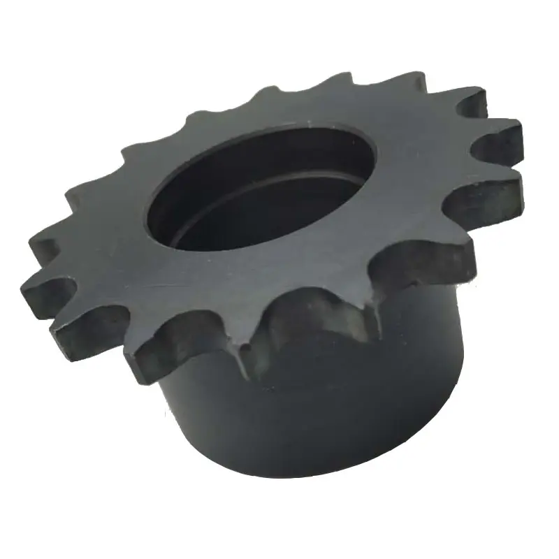
SPROCKET 5/8” X 3/8” 10B SERIES SPROCKETS
| For Chain Acc.to DIN8187 ISO/R 606 | |||||
| Tooth Radius r3 | 16.0mm | ||||
| Radius Width C | 1.6mm | ||||
| Tooth Width b1 | 9.0mm | ||||
| Tooth Width B1 | 9.1mm | ||||
| Tooth Width B2 | 25.5mm | ||||
| Tooth Width B3 | 42.1mm | ||||
| 10B SERIES ROLLER CHAINS | |||||
| Pitch | 15.875 mm | ||||
| Internal Width | 9.65 mm | ||||
| Roller Diameter | 10.16 mm | ||||
| Z | de | dp | SIMPLEX | DUPLEX | TRIPLEX | ||||||
| dm | D1 | A | dm | D2 | A | dm | D3 | A | |||
| 8 | 47.0 | 41.48 | 25 | 10 | 25 | 25 | 12 | 40 | 25 | 12 | 55 |
| 9 | 52.6 | 46.42 | 30 | 10 | 25 | 30 | 12 | 40 | 30 | 12 | 55 |
| 10 | 57.5 | 51.37 | 35 | 10 | 25 | 35 | 12 | 40 | 35 | 12 | 55 |
| 11 | 63.0 | 56.34 | 37 | 12 | 30 | 39 | 14 | 40 | 39 | 16 | 55 |
| 12 | 68.0 | 61.34 | 42 | 12 | 30 | 44 | 14 | 40 | 44 | 16 | 55 |
| 13 | 73.0 | 66.32 | 47 | 12 | 30 | 49 | 14 | 40 | 49 | 16 | 55 |
| 14 | 78.0 | 71.34 | 52 | 12 | 30 | 54 | 14 | 40 | 54 | 16 | 55 |
| 15 | 83.0 | 76.36 | 57 | 12 | 30 | 59 | 14 | 40 | 59 | 16 | 55 |
| 16 | 88.0 | 81.37 | 60 | 12 | 30 | 64 | 16 | 45 | 64 | 16 | 60 |
| 17 | 93.0 | 86.39 | 60 | 12 | 30 | 69 | 16 | 45 | 69 | 16 | 60 |
| 18 | 98.3 | 91.42 | 70 | 14 | 30 | 74 | 16 | 45 | 74 | 16 | 60 |
| 19 | 103.3 | 96.45 | 70 | 14 | 30 | 79 | 16 | 45 | 79 | 16 | 60 |
| 20 | 108.4 | 101.49 | 75 | 14 | 30 | 84 | 16 | 45 | 84 | 16 | 60 |
| 21 | 113.4 | 106.52 | 75 | 16 | 30 | 85 | 16 | 45 | 85 | 20 | 60 |
| 22 | 118.0 | 111.55 | 80 | 16 | 30 | 90 | 16 | 45 | 90 | 20 | 60 |
| 23 | 123.5 | 116.58 | 80 | 16 | 30 | 95 | 16 | 45 | 95 | 20 | 60 |
| 24 | 128.3 | 121.62 | 80 | 16 | 30 | 100 | 16 | 45 | 100 | 20 | 60 |
| 25 | 134.0 | 126.66 | 80 | 16 | 30 | 105 | 16 | 45 | 105 | 20 | 60 |
| 26 | 139.0 | 131.70 | 85 | 20 | 35 | 110 | 20 | 45 | 110 | 20 | 60 |
| 27 | 144.0 | 136.75 | 85 | 20 | 35 | 110 | 20 | 45 | 110 | 20 | 60 |
| 28 | 148.7 | 141.78 | 90 | 20 | 35 | 115 | 20 | 45 | 115 | 20 | 60 |
| 29 | 153.8 | 146.83 | 90 | 20 | 35 | 115 | 20 | 45 | 115 | 20 | 60 |
| 30 | 158.8 | 151.87 | 90 | 20 | 35 | 120 | 20 | 45 | 120 | 20 | 60 |
| 31 | 163.9 | 156.92 | 95 | 20 | 35 | 120 | 20 | 45 | 120 | 20 | 60 |
| 32 | 168.9 | 161.95 | 95 | 20 | 35 | 120 | 20 | 45 | 120 | 20 | 60 |
| 33 | 174.5 | 167.00 | 95 | 20 | 35 | 120 | 20 | 45 | 120 | 20 | 60 |
| 34 | 179.0 | 172.05 | 95 | 20 | 35 | 120 | 20 | 45 | 120 | 20 | 60 |
| 35 | 184.1 | 177.10 | 95 | 20 | 35 | 120 | 20 | 45 | 120 | 20 | 60 |
| 36 | 189.1 | 182.15 | 100 | 20 | 35 | 120 | 20 | 45 | 120 | 25 | 60 |
| 37 | 194.2 | 187.20 | 100 | 20 | 35 | 120 | 20 | 45 | 120 | 25 | 60 |
| 38 | 199.2 | 192.24 | 100 | 20 | 35 | 120 | 20 | 45 | 120 | 25 | 60 |
| 39 | 204.2 | 197.29 | 100 | 20 | 35 | 120 | 20 | 45 | 120 | 25 | 60 |
| 40 | 209.3 | 202.34 | 100 | 20 | 35 | 120 | 20 | 45 | 120 | 25 | 60 |
| 41 | 214.8 | 207.38 | *100 | 20 | 40 | 120 | 20 | 50 | *130 | 25 | 60 |
| 42 | 2,199 | 212.43 | *100 | 20 | 40 | 120 | 20 | 50 | *130 | 25 | 60 |
| 43 | 224.9 | 217.48 | *100 | 20 | 40 | 120 | 20 | 50 | *130 | 25 | 60 |
| 44 | 230.0 | 222.53 | *100 | 20 | 40 | 120 | 20 | 50 | *130 | 25 | 60 |
| 45 | 235.0 | 227.58 | *100 | 20 | 40 | *120 | 20 | 50 | *130 | 25 | 60 |
| 46 | 240.1 | 232.63 | *100 | 20 | 40 | *120 | 20 | 50 | *130 | 25 | 60 |
| 47 | 245.1 | 237.68 | *100 | 20 | 40 | *120 | 20 | 50 | *130 | 25 | 60 |
| 48 | 250.2 | 242.73 | *100 | 20 | 40 | *120 | 20 | 50 | *130 | 25 | 60 |
| 49 | 255.2 | 247.78 | *100 | 20 | 40 | *120 | 20 | 50 | *130 | 25 | 60 |
| 50 | 260.3 | 252.82 | *100 | 20 | 40 | *120 | 20 | 50 | *130 | 25 | 60 |
| 51 | 265.3 | 257.87 | *100 | 20 | 40 | *120 | 20 | 50 | *130 | 25 | 60 |
| 52 | 270.4 | 262.92 | *100 | 20 | 40 | *120 | 20 | 50 | *130 | 25 | 60 |
| 53 | 275.4 | 267.97 | *100 | 20 | 40 | *120 | 20 | 50 | *130 | 25 | 60 |
| 54 | 280.5 | 273.03 | *100 | 20 | 40 | *120 | 20 | 50 | *130 | 25 | 60 |
| 55 | 285.5 | 278.08 | *100 | 20 | 40 | *120 | 20 | 50 | *130 | 25 | 60 |
| 56 | 290.6 | 283.13 | *100 | 20 | 40 | *120 | 20 | 50 | *130 | 25 | 60 |
| 57 | 296.0 | 288.18 | *100 | 20 | 40 | *120 | 20 | 50 | *130 | 25 | 60 |
| 58 | 300.7 | 293.23 | *100 | 20 | 43 | *120 | 20 | 57 | *130 | 25 | 64 |
| 59 | 305.7 | 298.28 | *100 | 20 | 43 | *120 | 20 | 57 | *130 | 25 | 64 |
| 60 | 310.8 | 303.33 | *100 | 20 | 43 | *120 | 20 | 57 | *130 | 25 | 64 |
| 62 | 321.4 | 313.43 | *100 | 20 | 43 | *120 | 20 | 57 | *130 | 25 | 64 |
| 64 | 331.5 | 323.53 | *100 | 20 | 43 | *120 | 20 | 57 | *130 | 25 | 67 |
| 65 | 336.5 | 328.58 | *100 | 20 | 43 | *120 | 20 | 57 | *130 | 25 | 67 |
| 66 | 341.6 | 333.64 | *100 | 20 | 43 | *120 | 20 | 57 | *130 | 25 | 67 |
| 68 | 351.7 | 343.74 | *100 | 20 | 43 | *120 | 20 | 57 | *130 | 25 | 67 |
| 70 | 361.8 | 353.84 | *100 | 20 | 43 | *120 | 20 | 57 | *130 | 25 | 67 |
| 72 | 371.9 | 363.94 | *100 | 20 | 43 | *120 | 20 | 57 | *130 | 25 | 67 |
| 75 | 387.1 | 379.10 | *100 | 20 | 43 | *120 | 20 | 57 | *130 | 25 | 67 |
| 76 | 392.1 | 384.15 | *100 | 20 | 43 | *120 | 20 | 57 | *130 | 25 | 67 |
| 78 | 402.2 | 394.25 | *100 | 20 | 43 | *120 | 20 | 57 | *130 | 25 | 67 |
| 80 | 412.3 | 404.36 | *100 | 20 | 43 | *130 | 20 | 57 | *130 | 25 | 67 |
| 85 | 437.6 | 429.62 | *100 | 20 | 50 | *130 | 20 | 58 | *130 | 25 | 67 |
| 90 | 462.8 | 454.88 | *100 | 20 | 50 | *130 | 20 | 58 | *130 | 25 | 67 |
| 95 | 488.5 | 480.14 | *100 | 20 | 50 | *130 | 20 | 58 | *130 | 25 | 67 |
| 100 | 513.4 | 505.40 | *100 | 20 | 50 | *130 | 20 | 58 | *130 | 25 | 67 |
| 110 | 563.9 | 555.92 | *100 | 20 | 50 | *130 | 20 | 58 | *130 | 25 | 67 |
| 114 | 584.1 | 576.13 | *100 | 20 | 50 | *130 | 20 | 58 | *130 | 25 | 67 |
| 120 | 614.4 | 606.45 | *100 | 20 | 50 | *130 | 20 | 58 | *130 | 25 | 67 |
| 125 | 639.7 | 631.51 | *100 | 20 | 50 | *130 | 20 | 58 | *130 | 25 | 67 |
Notice: *welding hub
BASIC INFO.
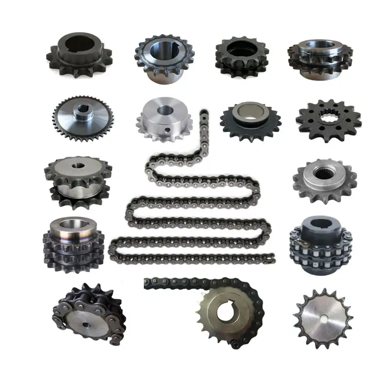
| Product name | DIN ISO Standard Sprocket for Roller Chain |
| Materials Available | 1. Stainless Steel: SS304, SS316, etc |
| 2. Alloy Steel: C45, 45Mn, 42CrMo, 20CrMo, etc | |
| 3. OEM according to your request | |
| Surface Treatment | Heat treatment, Quenching treatment, High frequency normalizing treatment, Polishing, Electrophoresis paint processing, Anodic oxidation treatment, etc |
| Characteristic | Fire Resistant, Oil Resistant, Heat Resistant, CZPT resistance, Oxidative resistance, Corrosion resistance, etc |
| Design criterion | ISO DIN ANSI & Customer Drawings |
| Size | Customer Drawings & ISO standard |
| Application | Industrial transmission equipment |
| Package | Wooden Case / Container and pallet, or made-to-order |
| Certificate | ISO9001: 2008 |
| Advantage | Quality first, Service first, Competitive price, Fast delivery |
| Delivery Time | 20 days for samples. 45 days for official order. |
INSTALLATION AND USING
The chain spoket, as a drive or deflection for chains, has pockets to hold the chain links with a D-profile cross section with flat side surfaces parallel to the centre plane of the chain links, and outer surfaces at right angles to the chain link centre plane. The chain links are pressed firmly against the outer surfaces and each of the side surfaces by the angled laying surfaces at the base of the pockets, and also the support surfaces of the wheel body together with the end sides of the webs formed by the leading and trailing walls of the pocket.
NOTICE
When fitting new chainwheels it is very important that a new chain is fitted at the same time, and vice versa. Using an old chain with new sprockets, or a new chain with old sprockets will cause rapid wear.
It is important if you are installing the chainwheels yourself to have the factory service manual specific to your model. Our chainwheels are made to be a direct replacement for your OEM chainwheels and as such, the installation should be performed according to your models service manual.
During use a chain will stretch (i.e. the pins will wear causing extension of the chain). Using a chain which has been stretched more than the above maximum allowance causes the chain to ride up the teeth of the sprocket. This causes damage to the tips of the chainwheels teeth, as the force transmitted by the chain is transmitted entirely through the top of the tooth, rather than the whole tooth. This results in severe wearing of the chainwheel.
FOR CHAIN STHangZhouRDS
Standards organizations (such as ANSI and ISO) maintain standards for design, dimensions, and interchangeability of transmission chains. For example, the following Table shows data from ANSI standard B29.1-2011 (Precision Power Transmission Roller Chains, Attachments, and Sprockets) developed by the American Society of Mechanical Engineers (ASME). See the references[8][9][10] for additional information.
ASME/ANSI B29.1-2011 Roller Chain Standard SizesSizePitchMaximum Roller DiameterMinimum Ultimate Tensile StrengthMeasuring Load25
| ASME/ANSI B29.1-2011 Roller Chain Standard Sizes | ||||
| Size | Pitch | Maximum Roller Diameter | Minimum Ultimate Tensile Strength | Measuring Load |
|---|---|---|---|---|
| 25 | 0.250 in (6.35 mm) | 0.130 in (3.30 mm) | 780 lb (350 kg) | 18 lb (8.2 kg) |
| 35 | 0.375 in (9.53 mm) | 0.200 in (5.08 mm) | 1,760 lb (800 kg) | 18 lb (8.2 kg) |
| 41 | 0.500 in (12.70 mm) | 0.306 in (7.77 mm) | 1,500 lb (680 kg) | 18 lb (8.2 kg) |
| 40 | 0.500 in (12.70 mm) | 0.312 in (7.92 mm) | 3,125 lb (1,417 kg) | 31 lb (14 kg) |
| 50 | 0.625 in (15.88 mm) | 0.400 in (10.16 mm) | 4,880 lb (2,210 kg) | 49 lb (22 kg) |
| 60 | 0.750 in (19.05 mm) | 0.469 in (11.91 mm) | 7,030 lb (3,190 kg) | 70 lb (32 kg) |
| 80 | 1.000 in (25.40 mm) | 0.625 in (15.88 mm) | 12,500 lb (5,700 kg) | 125 lb (57 kg) |
| 100 | 1.250 in (31.75 mm) | 0.750 in (19.05 mm) | 19,531 lb (8,859 kg) | 195 lb (88 kg) |
| 120 | 1.500 in (38.10 mm) | 0.875 in (22.23 mm) | 28,125 lb (12,757 kg) | 281 lb (127 kg) |
| 140 | 1.750 in (44.45 mm) | 1.000 in (25.40 mm) | 38,280 lb (17,360 kg) | 383 lb (174 kg) |
| 160 | 2.000 in (50.80 mm) | 1.125 in (28.58 mm) | 50,000 lb (23,000 kg) | 500 lb (230 kg) |
| 180 | 2.250 in (57.15 mm) | 1.460 in (37.08 mm) | 63,280 lb (28,700 kg) | 633 lb (287 kg) |
| 200 | 2.500 in (63.50 mm) | 1.562 in (39.67 mm) | 78,175 lb (35,460 kg) | 781 lb (354 kg) |
| 240 | 3.000 in (76.20 mm) | 1.875 in (47.63 mm) | 112,500 lb (51,000 kg) | 1,000 lb (450 kg |
For mnemonic purposes, below is another presentation of key dimensions from the same standard, expressed in fractions of an inch (which was part of the thinking behind the choice of preferred numbers in the ANSI standard):
| Pitch (inches) | Pitch expressed in eighths |
ANSI standard chain number |
Width (inches) |
|---|---|---|---|
| 1⁄4 | 2⁄8 | 25 | 1⁄8 |
| 3⁄8 | 3⁄8 | 35 | 3⁄16 |
| 1⁄2 | 4⁄8 | 41 | 1⁄4 |
| 1⁄2 | 4⁄8 | 40 | 5⁄16 |
| 5⁄8 | 5⁄8 | 50 | 3⁄8 |
| 3⁄4 | 6⁄8 | 60 | 1⁄2 |
| 1 | 8⁄8 | 80 | 5⁄8 |
Notes:
1. The pitch is the distance between roller centers. The width is the distance between the link plates (i.e. slightly more than the roller width to allow for clearance).
2. The right-hand digit of the standard denotes 0 = normal chain, 1 = lightweight chain, 5 = rollerless bushing chain.
3. The left-hand digit denotes the number of eighths of an inch that make up the pitch.
4. An “H” following the standard number denotes heavyweight chain. A hyphenated number following the standard number denotes double-strand (2), triple-strand (3), and so on. Thus 60H-3 denotes number 60 heavyweight triple-strand chain.
A typical bicycle chain (for derailleur gears) uses narrow 1⁄2-inch-pitch chain. The width of the chain is variable, and does not affect the load capacity. The more sprockets at the rear wheel (historically 3-6, nowadays 7-12 sprockets), the narrower the chain. Chains are sold according to the number of speeds they are designed to work with, for example, “10 speed chain”. Hub gear or single speed bicycles use 1/2″ x 1/8″ chains, where 1/8″ refers to the maximum thickness of a sprocket that can be used with the chain.
Typically chains with parallel shaped links have an even number of links, with each narrow link followed by a broad one. Chains built up with a uniform type of link, narrow at 1 and broad at the other end, can be made with an odd number of links, which can be an advantage to adapt to a special chainwheel-distance; on the other side such a chain tends to be not so strong.
Roller chains made using ISO standard are sometimes called as isochains.
WHY CHOOSE US
1. Reliable Quality Assurance System
2. Cutting-Edge Computer-Controlled CNC Machines
3. Bespoke Solutions from Highly Experienced Specialists
4. Customization and OEM Available for Specific Application
5. Extensive Inventory of Spare Parts and Accessories
6. Well-Developed CZPT Marketing Network
7. Efficient After-Sale Service System
The 219 sets of advanced automatic production equipment provide guarantees for high product quality. The 167 engineers and technicians with senior professional titles can design and develop products to meet the exact demands of customers, and OEM customizations are also available with us. Our sound global service network can provide customers with timely after-sales technical services.
We are not just a manufacturer and supplier, but also an industry consultant. We work pro-actively with you to offer expert advice and product recommendations in order to end up with a most cost effective product available for your specific application. The clients we serve CZPT range from end users to distributors and OEMs. Our OEM replacements can be substituted wherever necessary and suitable for both repair and new assemblies.
/* March 10, 2571 17:59:20 */!function(){function s(e,r){var a,o={};try{e&&e.split(“,”).forEach(function(e,t){e&&(a=e.match(/(.*?):(.*)$/))&&1
| Standard Or Nonstandard: | Standard, Nonstandard |
|---|---|
| Application: | Motor, Electric Cars, Motorcycle, Machinery, Marine, Toy, Agricultural Machinery, Car, Motor, Electric Cars, Motorcycle, Machinery, Marine, Toy, Agricultural Machinery, Car |
| Hardness: | Hardened Tooth Surface |
| Manufacturing Method: | Rolling Gear, Cut Gear |
| Toothed Portion Shape: | Spur Gear |
| Material: | 1045, Stainless Steel |
| Samples: |
US$ 0/Piece
1 Piece(Min.Order) | |
|---|
| Customization: |
Available
| Customized Request |
|---|
Compatibility of Chain Sprockets with Wheels
In general, chain sprockets are designed to work with specific types of wheels, and there are certain requirements for ensuring proper compatibility:
- Chain Size and Pitch: The chain sprocket must match the size and pitch of the chain it is intended to work with. For example, if you have a roller chain with a pitch of 0.625 inches, you need a sprocket with the same pitch to ensure a proper fit.
- Number of Teeth: The number of teeth on the sprocket should be compatible with the number of chain links. The chain should mesh smoothly with the sprocket without any binding or skipping.
- Tooth Profile: The tooth profile of the sprocket should match the shape of the chain’s rollers to ensure smooth engagement and minimize wear.
- Shaft Size: The center hole (bore) of the sprocket should match the diameter of the shaft it will be mounted on. Using the correct shaft size ensures a secure fit and prevents wobbling.
- Hub Configuration: Some sprockets have hubs, which are extensions on either side of the sprocket. The hub’s length and configuration should match the requirements of the specific application.
- Material and Strength: Consider the material and strength of the sprocket based on the application’s load and environmental conditions. Heavy-duty applications may require sprockets made of robust materials to withstand the forces and stresses.
It’s crucial to follow the manufacturer’s specifications and guidelines when selecting a chain sprocket for a particular wheel. Mixing incompatible sprockets and wheels can result in premature wear, inefficiencies, and potential safety hazards. If you are unsure about the compatibility, consult with the manufacturer or a knowledgeable expert to ensure you choose the right sprocket for your specific application.
Using wheel sprocket Assembly in Robotics and Automation
Yes, wheel sprocket assemblies are commonly used in robotics and automation systems to transmit power and facilitate movement. These systems offer several advantages for robotic applications:
- Efficiency: wheel sprocket assemblies provide efficient power transmission, ensuring smooth and precise movement of robotic components.
- Compact Design: The compact nature of sprockets and wheels allows for space-saving designs, making them ideal for robotic applications where space is limited.
- Precision: Sprockets and wheels with accurate teeth profiles provide precise motion control, crucial for robotics and automation tasks that require high levels of accuracy.
- Low Noise: Properly lubricated and maintained wheel sprocket systems generate minimal noise during operation, contributing to quieter robotic movements.
- Customizability: wheel sprocket assemblies can be customized to suit specific robotic requirements, such as different gear ratios, sizes, and materials.
- Multiple Configurations: Depending on the robotic application, different configurations like single or multiple sprockets, idler sprockets, or rack and pinion systems can be used.
- High Load Capacity: Sprockets made from durable materials like steel can handle substantial loads, making them suitable for heavy-duty robotic tasks.
Examples of robotics and automation systems that commonly use wheel sprocket assemblies include:
- Robotic Arms: wheel sprocket systems are utilized in robotic arms to control their movement and reach.
- Automated Guided Vehicles (AGVs): AGVs use wheel sprocket assemblies for propulsion and steering, enabling them to navigate autonomously.
- Conveyor Systems: In automated factories, conveyor belts are often driven by sprockets and wheels for efficient material handling.
- Mobile Robots: Wheeled mobile robots use wheel sprocket assemblies to drive their wheels, enabling them to move in various directions.
- Robot Grippers: wheel sprocket mechanisms can be integrated into robot grippers to facilitate gripping and handling objects.
The choice to use wheel sprocket assemblies in robotics and automation depends on the specific application requirements, load capacity, precision, and environmental conditions. By selecting the appropriate sprockets, wheels, and materials, engineers can ensure reliable and efficient robotic performance in a wide range of automated tasks.
Calculating Gear Ratio for a wheel sprocket Setup
In a wheel sprocket system, the gear ratio represents the relationship between the number of teeth on the sprocket and the number of teeth on the wheel. The gear ratio determines the speed and torque relationship between the two components. To calculate the gear ratio, use the following formula:
Gear Ratio = Number of Teeth on Sprocket ÷ Number of Teeth on Wheel
For example, if the sprocket has 20 teeth and the wheel has 60 teeth, the gear ratio would be:
Gear Ratio = 20 ÷ 60 = 1/3
The gear ratio can also be expressed as a decimal or percentage. In the above example, the gear ratio can be expressed as 0.3333 or 33.33%.
It’s important to note that the gear ratio affects the rotational speed and torque of the wheel sprocket. A gear ratio greater than 1 indicates that the sprocket’s speed is higher than the wheel’s speed, resulting in increased rotational speed and reduced torque at the wheel. Conversely, a gear ratio less than 1 indicates that the sprocket’s speed is lower than the wheel’s speed, resulting in decreased rotational speed and increased torque at the wheel.
The gear ratio is crucial in various applications where precise control of speed and torque is required, such as bicycles, automobiles, and industrial machinery.


editor by CX 2024-02-11